Safer, smarter, and better connected
Concepts for the Development of Battery Management Systems
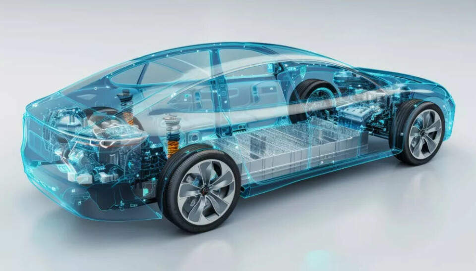
Current Battery Management Systems (BMS) must efficiently process voltage, current, and temperature measurements to ensure a safe operating state. More computing power and the advent of edge processing can be a solution here.
Car buyers expect not only more safety and comfort from their vehicles, but also increasing personalization. As a result, more software is being integrated into current cars, and a course towards the software-defined car has been set. This makes it possible for car manufacturers to fundamentally redesign the hardware and software architecture of their vehicles.
Domain and Zone Architectures
In the past, vehicles were equipped with additional MCUs when sensors or actuators demanded more intelligence, which inevitably increased the need for ever more complex control or communication structures. The additional complexity resulting from the variety of options of different vehicle platforms, in turn, increases development effort and makes maintenance a challenging task, and over-the-air updates also become time-consuming and complex.

Domain and zone architectures are intended to provide a remedy. In domain architectures (Figure 1), the MCUs are grouped according to their functions. In an electric vehicle (EV), for example, the on-board charger (OBC), the DC/DC converters, the traction inverter, and the battery management system (BMS) would be counted as part of the control domain and share a common MCU. OBC and traction inverter, for instance, should never be active simultaneously and could therefore easily share the computing capacity offered by the MCU.
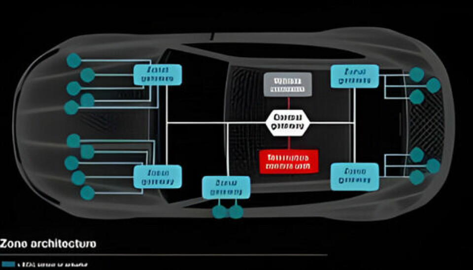
In zone architectures, the MCUs are not shared based on functional similarities, but rather according to their spatial location in the vehicle (Figure 2). The zones are interconnected with a broadband backbone, as the distributed sensors and actuators do not tolerate long delays in communication. Such zonal architectures require fewer MCUs and also reduce the complexity and weight of the wiring, which lowers costs and benefits the range.
Aimed at the ultimate goal of reducing the number of MCUs in the vehicle, domain-based and zonal architectures can even coexist in the same vehicle.
Challenges for a BMS
For a BMS, however, a crucial technical challenge arises because the recorded voltage, current, and temperature measurements are transmitted as raw data, while the available time frames for detecting errors, responding to errors, and establishing a safe operating state are strictly predefined. Therefore, the available bandwidth of the interface must be closely monitored and optimized, and the responsible domain or zone MCU must reserve appropriate time slots to ensure processing can occur within a specified interval.
These requirements can be mitigated by equipping the high-voltage chipset with more intelligence or by placing a smaller safety MCU at the edge of the BMS, for example in the form of a smart battery distribution box. This means that no raw data is transmitted to the central MCU, only the information whether everything is in order or not. Even though this concept runs counter to the actual goal of reducing the number of MCUs, the local MCU can use standardized interfaces (e.g., CAN-FD or Ethernet 10BASE-T1S) to insert an abstraction layer that makes it possible, for example, to source battery packs from different sources or to ensure vehicle, platform, or generational compatibility.
Intelligent BMS
At a very basic level, an MCU in a BMS is responsible for two tasks: it must receive data from sensors and transmit the information derived from it, which is relevant for functional safety and diagnostic tasks (e.g., the state of charge), to the BMS. Equipped with more computing power, the MCUs can also process more complex algorithms and provide the necessary intelligence to maximize the battery's utility. As batteries become larger, they also contain more cells, increasing the measurement effort accordingly, and not least, the voltages and energy content become greater. The growing number of signals requires MCUs with larger packages, especially as the transition from domain to zone architectures increases the need for inputs and outputs.
The increasing demands can be met with more computing power. While single-core MCUs with 100 MHz clock frequency were previously sufficient, multi-core components with up to 1 GHz clock frequency are now being used. The Arm Cortex-based 32-bit MCUs from TI, for example, provide the necessary computing power and energy efficiency for these applications.
The communication between the battery ECU and the rest of the vehicle is also becoming more complex, especially since the systems may need to take on different tasks depending on the current operating state of the vehicle. For example, it would make little sense to perform diagnostics or maintain cells at high speed. However, when the vehicle is connected to a charging station, more time and system bandwidth is available to perform these tasks and transmit information to the vehicle network - either wirelessly or via Ethernet. Depending on the degree of modularization realized, communication within the BMS may even be necessary.
MCUs in a BMS must not only be designed for functional safety, but also consider security aspects due to increasing connectivity. Additionally, it is important to provide support for open, standardized architectures such as AUTOSAR (Automotive Open System Architecture) to improve safety and reduce development times.
Wireless Communication
A significant advancement is the introduction of edge processing in wireless BMS solutions, as it improves the ability for real-time decisions, reduces latency, and optimizes the overall performance of automotive systems.
When data only needs to be transmitted to central ECUs to a minimal extent, the response time of adaptive battery management and dynamic energy distribution concepts is shortened, for example. With edge computing, a wireless BMS can analyze battery health, usage patterns, and environmental influences in real-time, allowing the system to adjust and optimize battery performance without delay. Lastly, local processing of critical data also reduces vulnerability to cyber attacks.
The software-defined radio solution from TI shown in Image 3 overcomes the restrictions of wired solutions and allows for a more creative, efficient integration into the complex architecture of software-defined vehicles.
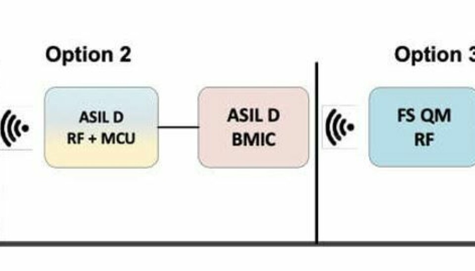
A wireless BMS can dynamically adapt to changing vehicle configurations, handle updates and modifications, and is therefore future-proof. Through protected communication protocols and redundancy, it also improves the reliability of the vehicle.
Intelligent Distribution Boxes
A pack monitor in an intelligent distribution box (Image 4) can measure voltages, currents, and insulation resistances.

Critical functions in a BMS are disconnecting the connection to the battery and power distribution (Image 5). Therefore, an intelligent battery distribution box contains not only the pack monitor but also contactor and pyro fuse drivers to be able to disconnect the battery pack from the other systems of the EV in the event of an accident. While pyro fuses are currently still mostly controlled by complex discrete circuits, TI has introduced the DRV3901-Q1, a highly integrated, safety-oriented solution for this task.
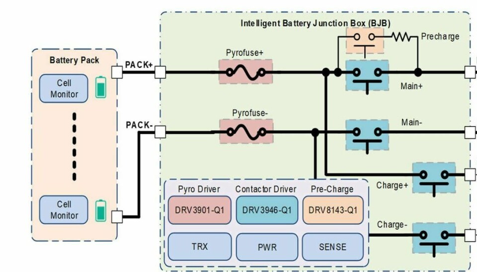
The contactors used for distributing power to the individual subsystems are often equipped with so-called economizer coils to reduce power consumption and heat generation. Contactors without this feature, on the other hand, require more complex, discrete control circuits to meet safety and efficiency requirements. The dual-channel contactor driver DRV3946-Q1 developed by TI provides a solution, offering more flexibility in design.
In intelligent battery distribution boxes, the isolated switch driver TPSI3100-Q1, with its isolated comparators and fault reporting outputs, can enhance diagnostic capabilities. Additionally, monitoring the required insulation resistance between the positive and negative poles of the traction battery and the vehicle ground is essential. Semiconductor relays like the TPSI2140-Q1 component switch a defined resistance, for example, 1 MΩ, in parallel to the resistance between the battery pole and ground, to then measure the total resistance with a pack monitor like the BQ79731-Q1 and decide whether it is still within the tolerance range.
Intelligent Functions
The software offers a variety of possibilities. By monitoring individual driving behavior, traffic conditions, topographical conditions, and road conditions, more precise range estimates can be made, and by storing data in the cloud, early detection of certain failure patterns is possible, allowing for a preventive workshop visit. These are just two examples of how the BMS can form the basis for numerous innovative concepts. TI offers a complete portfolio of components for this application area, enabling modern vehicles to become smarter, safer, and better connected.
This contribution is based on materials from Texas Instruments.
This article was first published at all-electronics.de
